Here we discuss the interior and boot construction of the early 1967 Lotus Elan S3 S/E DHC, revealing things learned through disassembly, and through this subsequent re-assembly phase.
To my current unhappy surprise, the S3 S/E DHC interior cockpit fixtures are not documented anywhere I have found, and my memory of what it was is a blank. This creates a bit of a challenging puzzle, which I am determined to solve, and to enjoy working on, through all the head scratching.
I wish I had made notes and photos of the disassembly all those years ago. But to be young is to be impetuous, and it seemed the Lotus Master parts List (LMPL) and the Workshop Manual would be sufficient to answer any re-assembly questions.
Dash
The original dash has been modified:
- Disappear the cigar lighter and ashtray
- Replace combined water temp and oil pressure gauge with separate gauges
- Add a voltage gauge
It was in pretty raw shape with some ill-advised tampering evident (damn PO). I managed to correct enough of the defects to prepare it for re-veneer.

- Re-veneered in sapele for similar grain/color to original

Cockpit
S1S Masonite panels, a type of hard millboard, fasten along the door sills and surrounds, covering the steel reinforcing lattice of the side body along the passenger compartment. A word to the wise: avoid side impacts in an Elan.
Pasteboard, a softer, more flexible millboard, covers the space behind the seats, forming the rear cockpit bulkhead. These panels enclose open space in the body shell, and serve as a base on which to install carpet.
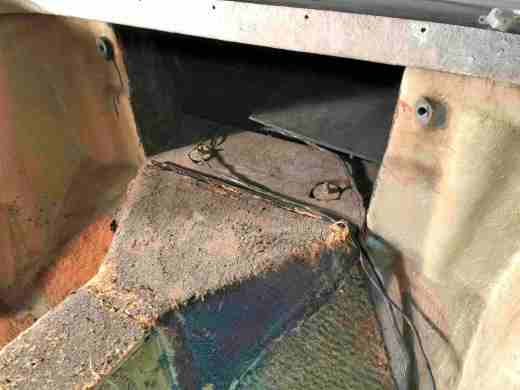
Here are stripped down views with panels removed, revealing the condition of unmodified bare body shell. Note the window frames have been re-plated in matte black chrome, because the owner dislikes shiny bits visible from the driver’s position.


The bulkhead millboard panel was broken in storage and needs a fiberglass patch to reconnect the pieces. Here is its back side in mid-patch, awaiting resin/glass application:

Fortunately I had saved all the carpet pieces and the millboard panels, and they tell most of the story. It appears the side panels go on first, then the rear bulkhead overlaps them. But the installed rear bulkhead then overlaps/conceals the lower outer seat belt anchors, meaning the seat belt is affixed before the bulkhead panel goes on. Then the belt must snake out between the overlap, of the side panel by bulkhead panel. Funny I wouldn’t remember something like that! Not so funny, it appears one has to partially disassemble the car’s interior to remove the seat belt.
All panels will be re-installed with glue where needed, and using original fasteners. The panels go as below, with partly-repaired bulkhead panel in place, overlapping the side panel.

The rear bulkhead fastens to a metal angle at the bottom across the tunnel. The bulkhead has three holes matching some holes in the angle. The LMPL confirms my observation that pop rivets were used, cut off during disassembly. I will replace with same.
The door Masonite panels have deteriorated along the edges due to moisture absorption; any handling or drilling risks crumpling or breaking of the edges, requiring glass mat and resin renovation. I repair them rather than re-cutting new ones, for the satisfaction of keeping as much original content as possible/desirable.
Since these panels are visible only after interior tear down, I am not very neat with my repairs. I have so much work ahead, I can’t afford to get fussy about inconsequential details. However unsightly, these hidden repairs make the items more functional.
I was surprised that the RH door surround panel was defective on both ends. The upper edge had not been drilled for attachment to the hood storage tray on top. The other end was broken off a few inches, below compared with the original LH side.


When drilling the top of the RH panel, I assumed the spacing of the holes would be the same on both sides, so used the LH panel as a template for the hole positions. From now on, I assume nothing regarding this fine example of Lotus engineering. The RH holes are 1/2 inch farther apart then those of the LH side.
Both RH panel defects have been fixed, with a drill and cardboard/fiberglass patch. This is turning out to be a real adventure. Apparently, the passenger side panel of my interior was held on by a #2 screw and the carpet adhesive. Sometimes, I wish I’d bought the Porsche.
Audio System
The car was not ordered with a radio, so no speakers were present when delivered. Early on I intended to install a cassette tape player, and so added speakers. As part of early interior/door work, the outer foot well cavities were converted to sealed (acoustic suspension) speaker enclosures with plywood speaker mounting baffles. Each cavity was further stuffed with sound-deadening material.
The original, hinge-articulated Masonite panels, used to enclose these foot well side cavities, will be stored as historical artifacts associated with this car, joining the original dynamo, voltage regulator, 2-bladed metal cooling fan, jack ratchet handle, clear hooters, and ash tray.
A pair of 1970-vintage Auratone 4.5″ 8Ω midrange drivers (paper cones, heavy square AlNiCo magnets) are mounted in each side’s enclosure. These speakers sounded great in their time; they were used in arrays (with different impedance) in a highly publicized retail speaker brand, were used in many recording studios as inexpensive monitors, and were used in factory car stereo systems through the 1990s and later. When installed in the same sealed cabinet, wired in parallel, each pair of speakers provides enhanced bass response while presenting a nominal 4Ω load.
Since the speakers are period-appropriate, still sound great, and nothing in today’s market would provide added value, I am happy to go forward with these speakers per original plan of 40 years ago.
Anticipating an earlier return to the road, I had long ago bought a cassette tape player, and subsequently a Blaupunkt CD receiver that fits the behind-dash space. These obsoleted devices were by far the largest expenditures sunk into an audio system. The cassette player seems to have gone in a garage sale at some point. The receiver still sits in a box unused; I will offer it on Ebay and recoup some of this premature, wasted expenditure.
The original installed drivers still appeared sound, until I noticed one cone had a tear and a hole. I removed it to repair the cone, but it failed an electrical continuity test, so I skipped the repair. Similar drivers in good condition are still available on Ebay. The one I bought (left below) is stamped CTS (Chicago Telephone Supply), not Auratone. But it is identical in every appearance detail, and both measure 7.5Ω static resistance; perhaps CTS supplied the Auratone drivers.

New carpet will be glued to the speaker baffle to maintain the foot well’s original look. A rectangular steel grille panel covers each speaker pair for protection. The carpet butts to the speakers under the edges of the grille. The grille-secured carpet edges are further treated with edge glue.
Today’s plan is to install a concealed, bare bones amp. The amp board is tiny and will be accessible if necessary from the removable radio blanking plate in the dash. In my usage, driving these speakers to listenable volumes, I estimate the amp will be working at ~10% of its rated power (about 5W or 500mA->4Ω). In a few years, when its capacitors dry out, the next owner can spend a few minutes and a few dollars to replace the board.

The board couples two off-the-shelf modules, a voltage regulator and a stereo amp. The SW-M16 (generic China Corp.) step-up transformer converts the car’s 12V battery input to 24V. It’s output maxes at about 5A, but it will generally need to supply only about 1A. The other module is the TI TPA3116D2 packaged by Drok, a D-class power amplifier providing 50W/channel at 0.1% THD. Perhaps <10W is all that’s necessary for driving the 4.2Ω speaker load to loud levels, so the system operates in its lowest distortion region. The complete kit is velcroed to the top of the heater blower enclosure.
After installing the replacement driver, checked out the polarity of the wiring with a speaker pop test, then hooked up the speaker cables to the output terminals of the amp board, to test the speaker performance before permanently sealing the four drivers to the baffle boards. Each speaker cable measures 4.2Ω static resistance at the amp board.
The sound is as I recalled: great midrange, with enough of deep bass to satisfy; very acceptable for car audio. The power supply drives the speakers to impressive volume levels, and the IC’s heat sink gets only slightly warm.
I have 350 songs from the ’60s on an iPhone playlist, with as many for other decades as well. They bring the Elan alive for the first time in 40 years. I’m glad I increased the priority of the restored audio system functionality, because it breathes life into the Elan carcass, brings me back to the period of this model, and inspires me to keep working toward the goal.
A bluetooth/AptX mobile handset interface will maintain a handset’s charge via USB connection while enabling wireless, handsfree, conversing on the phone or playing favorite tunes with maximum BT fidelity, all with Siri voice control. This great-sounding audio capability has required an investment of less than 100USD.
I’m not a big fan of car audio, due to its degrading environmental interactions, particularly in a drophead. But I still like to have my tunes travel with me, and sound great when I listen to them. My hearing is another reason I am less concerned with ultimate audio fidelity; at this stage of life, my measurable hearing response lies under 10kHz. Since these speakers will offer a frequency range beyond the hearing capability of most adult human ears, I am leaving further sophistication as an option for a subsequent owner/tweaker.
Electrical And other Metallic Parts
The rear part of the wiring loom looks great; no repairs needed. Thank you, garage rats.
All bare metal contacts looked great, after wire-brushing with a spray of WD-40 to clean corrosion and rust from the battery cable connectors, the battery ground connection to its boot bobbin, the rear light sockets, and the boot lid latch. All were then treated with a small amount of Permatex dielectric silicone grease prior to re-attachment.
If anyone knows what ‘court lights’ are, please give a shout. The loom has PW wiring branching to both sides of the car, which goes nowhere. In an online Workshop Manual wiring diagram (more detailed and up-to-date than that of my print Workshop Manual), it says they are for ‘court lights’, and there would be a switch on the door for same. It was perhaps available only on the Coupé, or only for non-export, or? It’s always nice to have extra resources. Now I hope I don’t lie awake at night devising uses for them.
The hot (-) lead from the battery to the solenoid goes over the LH rear turret, then down through the LH door sill, then up under the pedal mounting shaft before going through the firewall. I removed it to re-route it slightly in the foot well, so as to go around the LH speaker enclosure and over the pedal mounting shaft, cleaning up the foot well and giving a little extra length for maneuvering in the boot.
Boot
The gas tank interior condition is unknown. All the gas was drained 44 years ago. Can I just add gas and go, or must it be cleaned and reconditioned first? There is likely minor surface rust inside. When I get to the mechanical phase, I will try to get eyes on the interior somehow, as well as testing the plastic fuel line to the fuel pump, and replacing the connector tube between the metal fuel outlet pipe of the tank and the fuel line, which had become brittle and fallen apart.
Since I broke and scrapped the OEM jack early on, I acquired a nice aluminum scissors jack from a late 80’s RX7, together with a crank handle from a Toyota. If anyone can tell me the lifting platform dimensions for the OEM Elan jack, I can fabricate one for this jack. Leave a comment, please.
I liked the Porsche jacks, but they came too dear (although not by half what a used OEM Lotus junk jack goes for!). I regret that the jack handle cost more than the jack, but I got tired of trying to find a cheaper, used one.
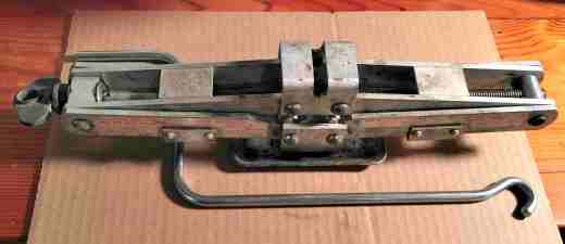
I had planned to relocate the battery under the rear scuttle between the rear turrets. But the scissors jack seems to fit well there, so I will leave the battery location as stock and devise a tie down for the jack. Both the jack and the battery will be hidden by removable carpeted panels, providing a clean interior for carrying nice stuffs.
The smaller-than-OEM battery can still be secured with the existing hardware, but with reversing one of the side clamps. This inexpensive AGM battery will complete the boot fitments. The original flooded battery had a footprint ~6″x9″ and was good for 39ah (aka heavy). The Deka Miata battery, made in USA, is only ~5″x7″, weighing 24 lbs., rated at 31ah. I like the lighter weight, and the car will be garaged in a mild climate. I got mine online, with a skimpy one year replacement warranty. (The local auto parts store sells a re-branded version with three year warranty, but with added core charge and sales tax, it would have cost 35% more. Since I have no exchange battery, I was persuaded to use the online source.)
This battery can be vented, since it was designed for enclosed boot service. A vent hole will be provided, out the boot to the LH rear wheel well, to accept the vent tube. A battery tender has been obtained, for easy connection to a garage outlet. It’s best to keep the smallish battery topped up for those periods when the car will not be run regularly, avoiding deep cycling as much as possible. The tender came with two sets of leads, one with alligator clamps, one with ring terminals. I have permanently attached the ring terminals to the battery cable clamps. When preparing to leave the car sitting for a while, the quick connect plug allows ready attachment of the charger, without requiring access to the battery.
Below I am testing the new battery and an inexpensive KeyLine Mini-Pro, a 5-stage, 1.5A battery tender, to ensure they are keepers. Being a new battery, the tender skipped the first desulfation mode of the automatic conditioning cycle. The charger launched bulk mode and took the voltage up to fully-charged state, then pushed voltage to 14.4V in absorption mode, at which point the current was reduced. The battery passed its 3 minute test in analysis mode, switching the charger to float mode. The voltage then gradually declined back to fully charged state, taking several days to fall to 12.9V and over a month to fall to 12.8V. Both pieces of equipment seem like winners; the battery is ready for boot installation.

The battery tray was cleaned and sprayed with satin black paint before receiving the battery. I prepared the spare tire well with flat black paint and visible surfaces of the fuel tank with satin black paint at the same time. In general, I tend to do metal surfaces in satin or crinkle/wrinkle/hammertone finish, and fiberglass in flat paint. I am treating the battery tray as if it were metal.
Early on in work on the car, I added some vertical fiberglass stiffening to the backlight panel, which had always seemed weak to me. I had never noticed until this picture that the reinforcements are not true vertical. No matter, now that experience has revealed a little of the car’s build quality, such workmanship seems entirely compatible with Lotus standards. And since it will not be visible in the completed project, I am not going to lose sleep over it, but will attempt to do a little nicer job going forward.

The stiffening protrusions required relief of the rear edge of the removable boot floor (plywood spare wheel cover), plus two cutouts at the top of the millboard backlight panel liner, aka boot wall (LMPL). Neither mod will be visible when boot interior is finished.
Aside: Has any production car of the last 50 years used this much millboard in its structure? It all still seems serviceable after 50 years, so can’t complain too much.
The original boot wall has gone tatty, even with only mild use over 5 years.

Blacking the surface blemishes with an indelible marker, followed by black boot polish, simulates original appearance. The four #10 1/2″ screws and washers for mounting the boot wall went missing, but matching equivalents were available in my lifetime collection of random fasteners.
Carpeting
Carpet, in 80/20 rayon/nylon (raylon) loop pile, 24oz/yard^2, with latex-backing, is readily available in black and seems as close as possible to the original S3/SE carpet.
Having laid out all the old carpet pieces, removed more than four decades ago, it appears the project can squeeze by with two ~6′ squares (if two odd shaped triangular pieces are reused behind the lower parts of the seats; they still look new). Ready-cut carpet for the Elan, including boot, used to run ~$500 plus shipping. It seems worth the $300 price difference to cut it on site. Then the car should end up with the same carpet appearance as the OEM carpet.

Four yards of carpet (ordered 72″ width, received 80″ width) came direct from the Dorsett Alabama factory, nice looking goods. The extra width will enable all required pieces to be cut, an unexpected bonus. It seems slightly heavier than the original, but with the same appearance. I plan to first re-carpet the boot, to gain experience before performing similar magic on the more complicated and visible cockpit.
When knowing so little about automotive carpeting, one tries to learn what tool works best to cut the carpet; what technique works best for laying out the pattern; what mastic or glue works best for adhering the carpet and underlying panels; what new underlayment technologies work best. Any tips greatly appreciated.
Safety Belts
The early 1967 Elan S3/SE came fitted with the OEM Teleflex inertial reel safety belts. Nothing is apparently known about these now, judging from the total absence of Internet chatter. These might be the only working pair left; hoping to hear from someone else who still uses them.

All the original mounting hardware for belts was found in a single glass jar – thank you, PO. The three mounting points for each seat are easily identified, with carpet and rear bulkhead pasteboard removed. The belt configuration seems intuitive, but I have been hoping for a picture to confirm my best guess. One surfaced in an old R&T issue from Nov 1967, which confirms how it seemed they must go, and also which goes on which side.

From the Elan Owner’s Manual that shipped with this car:

Inexplicably, the thread in the LH turret bobbin, for mounting the inertial reel device, is misaligned with the access hole; it no longer readily accepts any bolt of the correct size and thread. Hopefully, the access hole and its bobbin can be reworked in place.
The harness hardware should freshen up well enough, although the chromed tangs have some moderate pitting. They will be removed and re-plated. The inertial reel housing will be repainted black. The inertial mechanisms still work perfectly, and the belts show no noticeable wear or deterioration.
My banshee driving days being past, I have not considered a roll bar addition. That will be something for the next owner to fuss over. And if the worst comes to pass regarding this decision, it will be fitting, for each wife in their turn has commented that I deserve to be buried in ‘that (adjectives suppressed) yellow car’.
Seats
The seats are in great shape. They just need cleaning and dressing. First, some minor surface rust will be removed from the seat frames and floor mounting brackets, followed by re-spraying in black.
When assessing the seats, I initially could not find the eight seat rail mounting bolts. The LMPL shows them each as commonly available, 1/4″x3/4″ bolt with stover nut and washer. Happily, after more inventory accounting, I found another small parts cache, and there they were, a baggie with 8 1/4″ hex bolts, 8 washers, and 8 nuts, appearing to be nylocs (thank you PO). The bolts surprisingly have differing lengths, from 0.875″ to 1.25″. Wonder if I will find a reason behind this, or again, just luck of the draw from the Lotus parts bin? The thickness of the S/E carpeting probably necessitated added length.
Center Console
The entire passenger-side skirt of the plastic center console cover has broken off. I will try to repair it, but it likely will not be satisfactory. The back-up is to get a replacement ABS console cover and affix the original vinyl padding to the top.
The under-dash skirts must also be repaired or replaced. These OEM plastic parts were not of suitable quality, becoming very fragile over decades and breaking with slight contact.
Status Summary
Up until now, only the low-hanging fruit from the interior has been discussed. After this, it gets more challenging, door panels, dash, and behind-dash ancillaries. So far into assessment, nothing appears to have gone missing.
Proceed to Restoration ΦIV.

“Court Light” ……Courtesy lights (interior)
Thx John. Makes sense. But wonder why they sprout from rear loom and go nowhere on my early S3 DHC?
The wiring harness provides for the hardtop version of the Elan, as well as the DHC. In the hardtop, there are two interior lights (courtesy lights). There is no place for those interior lights in a DHC (no top), even thought you have wiring for them.